Modular System Interio

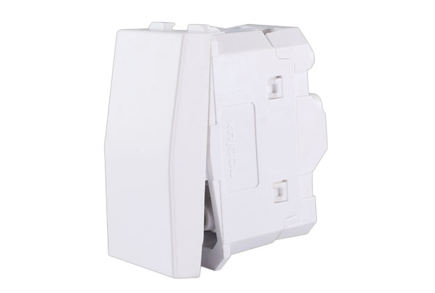
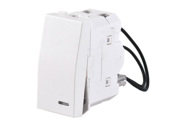
Switches 16AX 250V~ 1M
The design ensures implementation of all safety requirements prescribed by international standards.
 Technical data
SAFETY
The design ensures implementation of all safety requirements prescribed by international standards.
SWITCHES
160AX switch contacts.
Long life, in compliance with the requirements of the IEC standard. 40,000 operations (20,000 ONs and 20,000 OFFs).
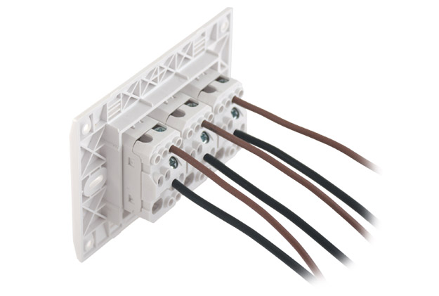
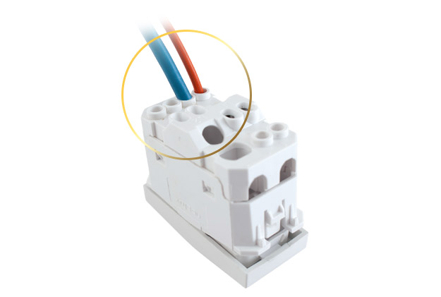
Screw-type terminals for safe acceptance of conductors with a cross-section of 1.5-2.5mm2. High barriers between the terminals provide safety against conductor short circuits.
The optimum wire length is engraved on the housing.
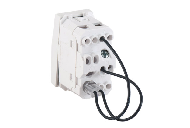
The product number, rated characteristics and the connection diagram are printed on the housing.
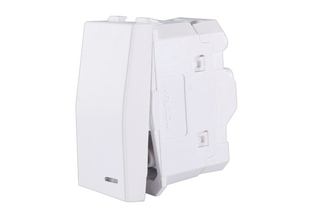
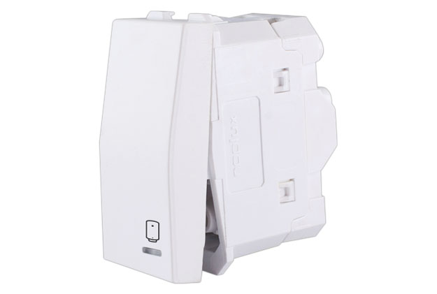
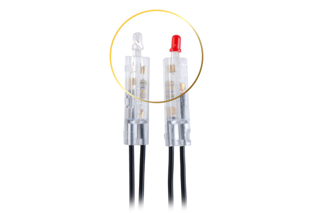
A switch can be illuminated by an indicator lamp or a location lamp depending on the purpose.
-
The indicator lamp is red and is used to indicate the on-state of the switch when the consumer is not in the field of view.
The switch with an indicator lamp has an embedded terminal for a neutral conductor. The location lamp is used for the night-time illumination of a switch; it is blue and illuminates the switch in its off-state.
 Module installation
MODULE INSTALLATION
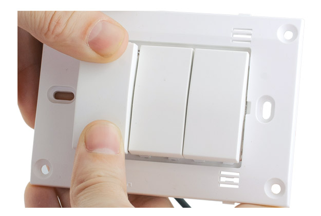
A module is installed into a supporting frame by manual inserting. All modules, except the Schuko socket-outlet module, can be installed without removing the plastic mask.
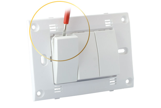
Modules can be detached from the supporting frame easily using a screwdriver so that the terminals are always accessible at the front. The supporting frame remains attached to the installation box. All the modules, except for the Shuko socket-outlet module, are removed without taking off the plastic mask.
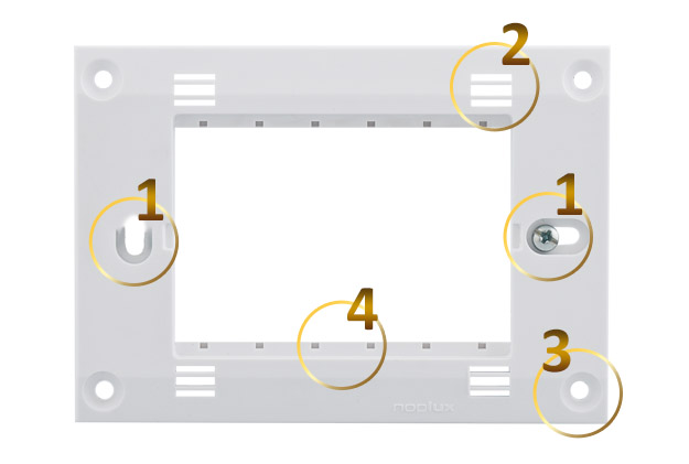
1. Adjusting holes along the x and y axes.
2. Holes for fastening the cover plate. The cover plate fastening holes are complemented with supporting holes, which increases resilience of the entire attachment system.
3. Cone-shaped points for non-standard attachment ensure significant flexibility in the installations as they enable direct installation where the use of boxes has not been envisaged or has proven impossible.
4. Module alignment.

At the rear, the whole supporting frame is reinforced with a net structure that strengthens it.
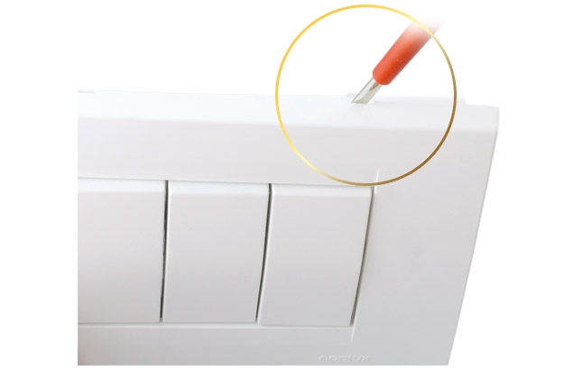
The cover plate is installed without the use of any tool by inserting it into the supporting frame.
Cover plate removal holes allow easy insertion of a screwdriver and de-installation of the cover plate without damaging it.


